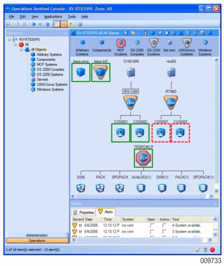
A topology provides a way to graphically depict all of the systems and consoles included in a view. An icon represents each system and console. See Figure 1–3. A topology graphically depicts systems, partitions, and consoles, including connection lines that represent the connections between items in a topology.
Connection Lines
The status of the connection between the Operations Sentinel server and the system or component is shown by a line around the system:
Solid green line indicates Operations Sentinel has established a connection to the managed object.
Red-dashed line indicates Operations Sentinel cannot establish a connection to the managed object or the status of the connection is unknown.
No line indicates Operations Sentinel is not monitoring that managed object.
Each OS 2200 system is represented with a vertical line to each of its consoles. No connection line is shown for arbitrary systems and components, since Operations Sentinel does not monitor their connection to Operations Sentinel.
Information Text Boxes
When you place the cursor over an icon, a text box of information for that object is superimposed on the topology.
Object Selection
When you left-click an icon or its label, the object represented by that icon is selected and highlighted with a shaded rectangle around its label. You can select multiple objects by holding the Ctrl key and clicking each icon or label. The Properties tab of the Details pane shows the common property values of the selected objects. The Alerts tab of the Details pane shows all alerts that apply to the selected objects.
Context Menu
When you right-click an icon, a menu of actions appears. Depending on the class of object and other factors, the menu can include the following:
Open console window
Open remote desktop
Open terminal window
View log
Display details