Sample TCP/IP Network Running OSI Applications illustrates a simple network configuration where each host in the network is configured with one OSI NSAP address and one TCP/IP IP address. However, in a more complex network configuration, a local or remote host in your network could be configured with multiple IP addresses (network paths) and/or multiple NSAP addresses.
For example, you have the following options:
-
Pairing one NSAP address to multiple IP addresses
-
Pairing one domain name address to multiple NSAP addresses
-
Identifying one IP address to pair with a specific NSAP address
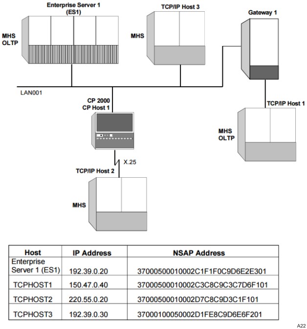
The preceding figure illustrates a sample TCP/IP configuration consisting of one enterprise server host and three other hosts (TCPHOST1, TCPHOST2, and TCPHOST3). In this example, assume the sample network is configured with the following IP addresses, domain names, and NSAP addresses.
|
Host |
IP Address |
Domain Name |
NSAP Address |
|---|---|---|---|
|
ES1 |
192.029.001.111 192.030.002.112 |
Not Identified |
3700050001000120 3700050001000121 |
|
TCPHOST1 |
Not Identified |
TCPHOST1.TREDY.BIGCO.COM |
3700050001000130 3700050001000131 |
|
TCPHOST2 |
220.055.000.020 |
Not Identified |
3700050001000140 |
|
TCPHOST3 |
192.031.003.113 |
TCPHOST3.TREDY.BIGCO.COM |
3700050001000150 |
Generating the Appropriate OSI Endpoints
Based on the information provided, the following OSI endpoints should already be configured in the OSI endpoint initialization file for ES1.
| Note: | To enable OSI applications to run over a TCP/IP network, you do not have to make any changes to existing OSI endpoint definitions. |
|
OSI Endpoint Needed to Enable |
Corresponding Command |
|---|---|
|
ES1 to run Open/OLTP applications |
NW ADD OSIEPN (FN = TPOSI, HN = ES1, NAME = "TP", APPLGRP = *BNA_HOST_SERV, PSEL = 5450, SSEL = 4F53495450, TSEL = O1, NSAPA = 3700050001000120) |
|
ES1 to run MHS applications |
NW ADD OSIEPN (FN = MHSOSI, HN = ES1, NAME = "X400MHS", HN = *BNA_HOST_SERV, SSEL = *NULL, TSEL = 01, NSAPA = 3700050001000121) |
|
TCPHOST1 to run Open/OLTP applications |
NW ADD OSIEPN (FN = TPOSI, HN = TCPHOST1, NAME = "TP", APPLGRP = *BNA_HOST_SERV, PSEL = 5450, SSEL = 4F53495450, TSEL = 01, NSAPA = 3700050001000130) |
|
TCPHOST1 to run MHS applications |
NW ADD OSIEPN (FN = MHSOSI, HN = TCPHOST1, NAME = "X400MHS", HN = *BNA_HOST_SERV, SSEL = *NULL, TSEL = 01, NSAPA = 3700050001000121) |
|
TCPHOST2 to run MHS applications |
NW ADD OSIEPN (FN = MHSOSI, HN = TCPHOST2, NAME = "X400MHS", HN = *BNA_HOST_SERV, SSEL = *NULL, TSEL = 01, NSAPA = 3700050001000121) |
|
TCPHOST3 to run MHS applications |
NW ADD OSIEPN (FN = MHSOSI, HN = TCPHOST3, NAME = "X400MHS", HN = *BNA_HOST_SERV, SSEL = *NULL, TSEL = 01, NSAPA = 3700050001000121) |
Pairing the Appropriate OSI-TCP/IP Addresses
If you do not care which network path ES1 selects as an outbound connection path when communicating with remote hosts TCPHOST1, TCPHOST2, and TCPHOST3, the following ADD NETWORK ADDRESS PAIR commands need to be added to your OSI initialization file.
|
Host |
Commands Placed in the OSI Initialization File |
|---|---|
|
ES1 |
NW ADD NETADDRPAIR NSAPA 3700050001000120 TO IPADDR 192.029.001.111 NW ADD NETADDRPAIR NSAPA 3700050001000120 TO IPADDR 192.030.002.112 NW ADD NETADDRPAIR NSAPA 3700050001000121 TO IPADDR 192.029.001.111 NW ADD NETADDRPAIR NSAPA 3700050001000121 TO IPADDR 192.030.002.112 |
|
TCPHOST1 |
NW ADD NETADDRPAIR NSAPA 3700050001000130 TO DN "TCPHOST1.TREDY.BIGCO.COM" NW ADD NETADDRPAIR NSAPA 3700050001000131 TO DN "TCPHOST1.TREDY.BIGCO.COM" |
|
TCPHOST2 |
NW ADD NETADDRPAIR NSAPA 3700050001000140 TO IPADDR 220.055.000.020 |
|
TCPHOST3 |
NW ADD NETADDRPAIR NSAPA 3700050001000150 TO IPADDR 192.039.000.030 DN "TCPHOST3.TREDY.BIGCO.COM" |
These commands enable the enterprise server to communicate with remote hosts TCPHOST1, TCPHOST2, and TCPHOST3 running OSI applications over either outbound connection path.
Identifying a Specific Outbound Path to Be Used for Communication
If you always want ES1 to use the same network path as an outbound connection when communicating with TCPHOST1 and TCPHOST3, you must configure your network accordingly.
Identifying the Destination Systems
Once you have identified the pairing between the host's IP address and its OSI NSAP address, you must identify which destination hosts the local host can communicate with. This is done on the OSI DESTINATION NETWORK ADDRESS PAIRS screen. To define the appropriate destination hosts to the local host, perform the following steps using the NAU:
-
On the SYSTEM LIST screen, specify on local host ES1. The OSI SYSTEM MENU screen displays.
-
Enter NAP in the Choice field and transmit the screen. The OSI DESTINATION NETWORK ADDRESS PAIRS screen displays.
-
Enter the name of the destination hosts with which the local host will communicate. For the sample, enter TCPHOST1, TCPHOST2, and TCPHOST3, and transmit the screen. The screen is refreshed.
-
Specify on TCPHOST1 (to further define the configuration so that ES1 will always use the same network path when it communicates with TCPHOST1). The LOCAL IP ADDRESS ASSIGNMENT screen displays with the Network Service Access Point Address field prefilled with TCPHOST1's NSAP addresses.
-
Enter the IP address of ES1 that you want to use as an outbound connection path to TCPHOST1; for the sample, enter 192.029.001.111 for both NSAP addresses.
-
Repeat these steps beginning with step 4 to define the same ES1 IP address to be used as an outbound connection path when communicating with TCPHOST3.
OI Commands Generated by the NAU
The NAU will place the following ADD NETWORK ADDRESS PAIR commands in the ES1 OSI initialization file:
