The following topics, “Same Network/Subnet” and “Alternate Networks/Subnets,” provide a description of solutions for handling multiple parallel routes by TCPIPSUPPORT. These solutions are supported on IPv4 and IPv6 networks.
Parallel Routes Through the Same Subnet and Parallel Routes Through Alternate Networks demonstrate network topologies designed to be fully connected and to have built-in redundancy, but do not necessarily provide the elimination of single points of failure. Parallel Routes Through the Same Subnet demonstrates the elimination of single points of failure while Parallel Routes Through Alternate Networks does not. Network redundancy, as demonstrated by both topologies, is achieved by providing more than one parallel path/route to and from common remote destinations. If one of these parallel routes fails, the alternate route is capable of handling the traffic for the network. Also note that when more than one parallel route is active, dialogs can effectively be balanced across the active routes such that no single next-hop router need handle the full traffic burden.
All redundant configurations, such as those described here, do not necessarily imply the capability for dialog resiliency. Redundancy and resiliency are not synonymous, nor does one imply the other. Achieving seamless dialog recovery (resiliency) in the event of a route failure requires that the networks within the topology eliminate any single point of failure.
Same Network/Subnet
Parallel Routes Through the Same Subnet demonstrates network redundancy in which there are multiple parallel routes using next-hop routers that are in the same network as the local host.
| Note: | Providing more than one route from the same network eliminates any single point of failure for that network. Such a topology also supports dialog resiliency on route failures. |
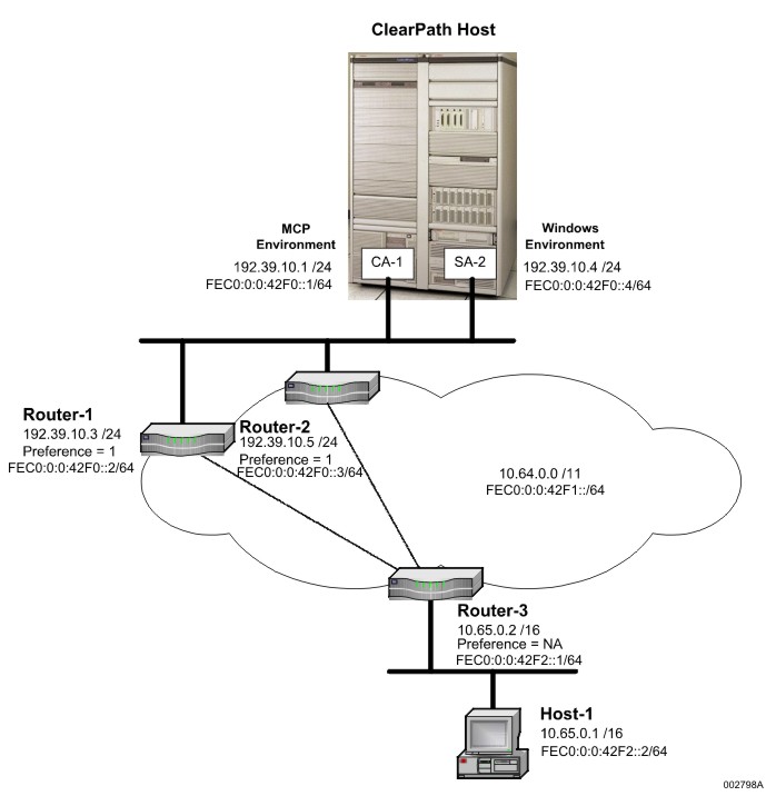
Route redundancy, as configured in Parallel Routes Through the Same Subnet, is provided by next-hops Router-1 and Router-2. If both routers are configured to have equal preference, dialogs between a remote destination and the local host will be balanced across each route. Should one of the next-hop routers fail, the other is capable of handling the complete dialog load until the failure can be corrected.
Not only is this topology redundant, it also offers route resiliency if one of the routers fail. Route resiliency can be supported by this topology because there is no single point of failure for routes to external destinations from network 192.39.10.0 /24. If either Router-1 or Router-2 fails, the other router still provides external routing capability.
For example, should next-hop Router-1 fail, dialogs using that next-hop will eventually report potential failure information to IP. Upon receiving this information, IP executes its Dead Gateway algorithm. When Dead Gateway determines that Router-1 has failed, an alternate route to the same destination, Router-2, is located and the dialogs are seamlessly rerouted through Router-2. This operation has no effect on the local network interface servicing the dialogs. Only the dialog's route cache has been updated to reflect the new next hop. The same network interface, SA-2, is used since the alternate route, via Router-2, is in the same network as the route that failed.
Alternate Networks/Subnets
Parallel Routes Through Alternate Networks demonstrates another form of network redundancy by configuring a network where there are alternate routes using next-hop routers that are not in the same network or subnetwork as the local host. Unlike Parallel Routes Through the Same Subnet, Parallel Routes Through Alternate Networks has single points of failure for routes to external destinations. While this topology is technically redundant and has more than a single route to external destinations, it does not provide dialog resiliency on route failures.
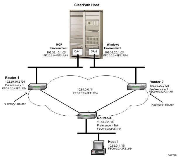
As shown in Parallel Routes Through Alternate Networks, route redundancy is provided by next-hops Router-1 and Router-2. Since each network only has a single route to external destinations (single point of failure), the loss of either Router-1 or Router-2 will force the termination of those dialogs using the route that failed. Dialog resiliency cannot be achieved in topologies where routes to external destinations are configured with a single point of failure.
In Parallel Routes Through Alternate Networks, Router-2 cannot act as a backup router for Router-1. While there is a mechanism to internally forward datagrams between the two networks, a host has no means of informing the external routers that a route to 192.39.10.1 (or FEC0:0:0:42F0::1/64 in an IPv6 network) still exists via Router-2 and subsequently via the local network interface at SA-2. External routers only know, and learn, routes that have been discovered through their router-to-router protocols. The best that can be expected is that Router-2 will eventually learn that Router-1 has failed and remove routes via Router-1 from its own routing tables thus enabling it to inform a host that CA-1 is no longer reachable by returning destination unreachable ICMP messages. Such a topology can be corrected to support dialog resiliency by configuring additional redundant routes for each network such that there is no longer any single point of failure.
The handling of multiple parallel routes through alternate networks becomes the same as handling parallel routes in the topic, “Same Network/Subnet." As the local host receives datagrams from a remote destination intended for logical network interface, 192.39.20.1 (SA-2), (or FEC0:0:0:42F3::2/64 in an IPv6 network), the shared adapter directs them to the MCP TCP/IP for processing. Since SA-2 is in a different network from CA-1, datagrams for 192.39.20.1 will only arrive over Router-2 and datagrams for 192.39.10.1 (CA-1) will only arrive over Router-1. If Router-1 fails, dialogs using Router-1 eventually terminate since they cannot be rerouted through a different network. Therefore, the shared adapter will not receive datagrams that are not for the local network interface owned by SA-2. New dialogs established to and from the local host will now only use the route via Router-2 and network interface SA-2.
Weak-Model Multihoming
“Weak-Model illustrates a topology known as weak-model multihoming since traffic entering a server uses a different path than the traffic exiting. This topology is supported only on IPv4 networks. Although this topology might not apply to all traffic processed by a server, it is typical of most remote traffic (one or more hops away).
There are two physical paths between the ClearPath server and the remote host, Host-1; one via Router-1 and another via Router-2. Since multiple routes can be configured to a destination, both paths to Host-1 can be configured. Routes can be defined for both Router-1 and Router-2.
Using preference values, one path using Router-1 could be designated as the “primary” route and the other using Router-2 as the “alternate” route. This would permit an organization to continue the use of a weak-model multihoming operation with one exception. If the primary route, Router-1, fails, there is now an alternate route, Router-2, available. While dialogs to and from the address assigned to CA-1 might no longer be possible (no viable path to network-prefix 192.39.10.0 /24), in‑progress dialogs to and from the address assigned to CA-2 can be rerouted and new dialogs with CA-2 can still be established.
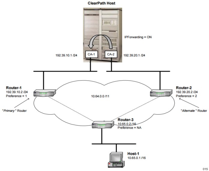
“Weak-Model illustrates a topology with single points of failure in network-prefix 192.39.10.0 /24 and 192.39.20.0 /24 as there is only one router that services each network. To eliminate the single points of failure, you can add additional routers within each network-prefix to increase resiliency, as shown in Resilient “Weak-Model.
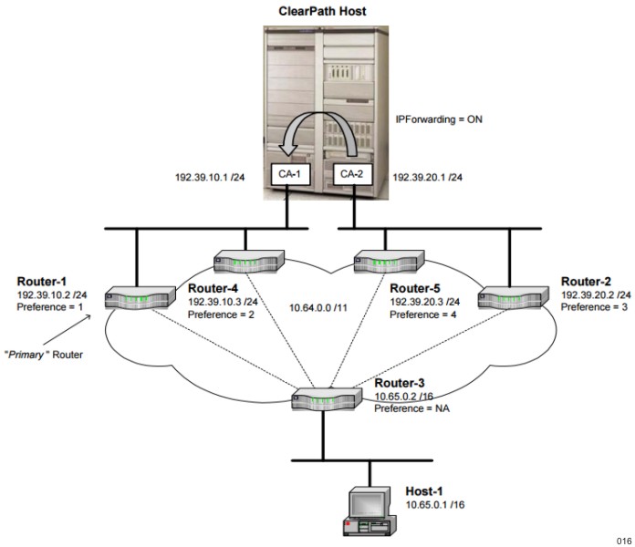
Unlike “Weak-Model, if Router-1 fails in Resilient “Weak-Model, there is still another router, Router‑4, capable of servicing that network-prefix. Here, all dialogs are preserved and new dialogs can still be established with both CA-1 and CA-2.
